2004 Ford250 Fuel Gauge Light on and Reading Empty and Now It Working
Fuel Estimate The instrument cluster receives the fuel level bespeak from the fuel level sensor, part of the fuel tank unit. The fuel level sensor measures variable resistance in the fuel tank depending on the current fuel level. When the fuel level is depression, the resistance in the unit of measurement is low (15 ohms +/- two ohms). When the fuel level is high, the resistance in the unit is high (160 ohms +/- 4 ohms). The instrument cluster uses iv different operating modes to summate the fuel level: � anti-slosh (default manner) � key OFF fueling � key ON fueling � recovery Subsequently a fuel make full upwards, the fourth dimension for the fuel approximate to move from empty (E) to total (F) ranges from two seconds to 55 minutes depending on which operating mode the fuel judge is in. The default fuel gauge style is called the anti-slosh mode. To prevent fuel estimate changes from fuel slosh (gauge instability due to changes in fuel sender readings caused by fuel moving around in the tank), the fuel gauge takes approximately 55 minutes to become from full (F) to empty (E). The cardinal OFF fueling mode (2 seconds to read empty [Due east] to full [F]) requires 3 conditions be met: � The key must be in the OFF position when refueling the vehicle. � At to the lowest degree 15 percent of the vehicle'southward fuel capacity must be added to the fuel tank. � The instrument cluster must receive a valid key ON fuel sender reading inside one 2d of the key being put into the RUN position. The key ON sample readings are considered valid if the fuel sender reading is between fifteen ohms +/- 2 ohms and 160 ohms +/- four ohms. If these conditions are non met, the fuel gauge stays in the anti-slosh mode, which results in a dull to read total (F) effect. The key ON fueling mode (approximately 90 seconds to read empty [East] to full [F]) requires 3 conditions be met: � The transmission is in park (P) (automatic transmissions), or the parking brake applied (manual transmissions). � The key is in the RUN position. � At least fifteen per centum of the vehicle'southward fuel chapters must exist added to the fuel tank. In central ON fueling manner, a xxx 2nd timer activates after the manual is put into the park (P) position (automated transmissions) or when the parking brake is applied (manual transmissions). When the 30 2nd time has elapsed and at to the lowest degree 15 percentage of the vehicle's fuel capacity has been added, the fuel gauge response time is 90 seconds to read from empty (Eastward) to full (F). When the transmission is shifted out of park (P) or the parking brake is released, the fuel gauge strategy reverts Annotation: It is critical to follow the pinpoint exam diagnostic methods to brand sure the correct fashion is being used during diagnostics. to the anti-slosh way. This mode prevents slow to read total events from happening if the client refuels the vehicle with the fundamental in the RUN position. Recovery mode is incorporated into the instrument cluster strategy to recover from a missing fuel level message during a refueling consequence. Missing fuel level messages result from intermittent opens in the fuel sender or its circuits. Recovery mode (empty [Eastward] to full [F] approximately xx minutes) is initiated when the post-obit two conditions are met: � The musical instrument cluster is in the anti-slosh (default) style. � The actual fuel level in the tank is greater than what is being displayed by the fuel gauge.
Testing:
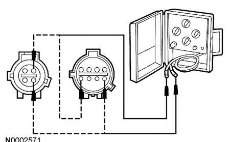
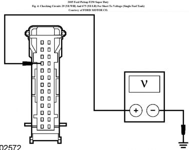
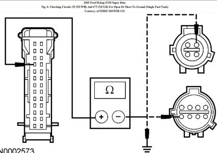
PINPOINT TEST B: INCORRECT FUEL Estimate INDICATION B1 CARRY OUT THE Instrument CLUSTER FUEL GAUGE ACTIVE COMMAND USING THE DIAGNOSTIC TOOL � Key in ON position. � Enter the following diagnostic mode on the diagnostic tool: Instrument Cluster Active Command. � Select the musical instrument cluster agile command. Trigger, monitor, and coil the fuel approximate level at 0%, l%, and 100%. � Does the fuel gauge display below East with 0%, half with 50%, and full terminate with 100%? � Yeah : GO to B2. � No : Become to B7. B2 Cheque THE FUEL Guess OPERATION � Key in OFF position. � Remove the fundamental junction box (CJB) fuses ii (10A), 35 (10A) and 41 (10A). Expect i minute and reinstall the fuses. � Disconnect: Fuel Tank Unit C434 (Pickup) or C4033 (Chassis Cab). � Connect ane lead of the instrument gauge system tester to the fuel tank unit of measurement C434-two (pickup) or C4033-5 (chassis cab), circuit 29 (YE/WH), harness side and the other lead to the fuel tank unit of measurement C434-4 (pickup) or C4033-8 (chassis cab), circuit 396 (BK/OG), harness side. Fig. 3: Checking Fuel Judge Functioning Courtesy of FORD MOTOR CO. � Fundamental in ON position. � On vehicles equipped with an automated manual, apply the restriction and motility the transmission shift lever from P (park) to D (drive). Wait ten seconds, and move the transmission shift lever dorsum to P (park). Await xxx seconds. On vehicles equipped with a transmission transmission, apply the parking brake. Wait x seconds, and release the parking brake. Wait 30 seconds. Do not modify the tool settings or the ignition switch position until xxx seconds have elapsed. � Fundamental in OFF position. � Set the tester to 160 ohms. � Cardinal in ON position. � On vehicles equipped with an automated manual, apply the brake and move the transmission shift lever from P (park) to D (drive). Expect 10 seconds, and movement the transmission shift lever back to P (park). Expect thirty seconds. On vehicles equipped with a manual manual, apply the parking restriction. Wait 10 seconds, and release the parking NOTE: The fuses must be removed to reset the fuel gauge timers. Failure to complete this step may result in erroneous test results. brake. Await thirty seconds. Do not change the tool settings or the ignition switch position until 30 seconds have elapsed. � Central in OFF position. � Wait thirty seconds. Do non change the tool settings or the ignition switch position until xxx seconds have elapsed. � Set the tester to 15 ohms. � Key in ON position. � On vehicles equipped with an automated transmission, apply the brake and motility the transmission shift lever from P (park) to D (bulldoze). Expect ten seconds, and motility the transmission shift lever back to P (park). Expect 30 seconds. On vehicles equipped with a manual transmission, apply the parking brake. Wait 10 seconds, and release the parking brake. Look thirty seconds. Do not modify the tool settings or the ignition switch position until 30 seconds accept elapsed. � Observe the fuel gauge. The fuel judge should read E (empty) or below. � Key in OFF position. � Wait 30 seconds. Practise not change the tool settings or the ignition switch position until thirty seconds have elapsed. � Set the tester to 160 ohms. � Key in ON position. Observe the fuel guess. The fuel gauge should read F (full ) or to a higher place. � Does the fuel approximate operate correctly? � Yes : DISCONNECT the instrument gauge system tester. Get to B3. � No : DISCONNECT the instrument judge system tester. GO to B4. B3 CHECK THE FUEL TANK � Bank check the fuel tank for whatever damage or deformation. � Is the fuel tank OK? � Aye : INSTALL a new fuel tank unit. REFER to FUEL TANK AND LINES - GASOLINE AND Diesel . CLEAR the DTCs. REPEAT the self-test. � No : INSTALL a new fuel tank. REFER to FUEL TANK AND LINES - GASOLINE AND Diesel . Articulate the DTCs. Repeat the self-test. B4 Check CIRCUITS 29 (YE/WH) AND 675 (YE/LB) FOR A Short TO VOLTAGE � Disconnect: Instrument Cluster C220b. � Key in ON position. � For vehicles equipped with a unmarried fuel tank, measure the voltage between the instrument cluster C220b-10, circuit 29 (YE/WH), harness side and ground. Fig. 4: Checking Circuits 29 (YE/WH) And 675 (YE/LB) For Short To Voltage (Single Fuel Tank) Courtesy of FORD MOTOR CO. NOTE: Wait one minute for the fuel gauge to respond. � For vehicles equipped with dual fuel tanks, measure the voltage betwixt the instrument cluster C220b-9, circuit 675 (YE/LB), harness side and basis. Fig. five: Checking Circuits 29 (YE/WH) And 675 (YE/LB) For Short To Voltage (Dual Fuel Tank) Courtesy of FORD MOTOR CO. � Is any voltage present? � Yep : REPAIR the circuit in question. CLEAR the DTCs. Echo the self-test. � No : GO to B5. B5 Check CIRCUITS 29 (YE/WH) AND 675 (YE/LB) FOR AN Open up OR A SHORT TO GROUND � For vehicles equipped with a unmarried fuel tank, measure out the resistance between the instrument cluster C220b-10, circuit 29 (YE/WH), harness side and the fuel tank unit C434-two (pickup) or C4033-5 (chassis cab), circuit 29 (YE/WH), harness side; and betwixt the instrument cluster C220b-ten, circuit 29 (YE/WH), harness side and footing. Fig. 6: Checking Circuits 29 (YE/WH) And 675 (YE/LB) For Open Or Brusk To Ground (Single Fuel Tank) Courtesy of FORD MOTOR CO. � Disconnect: Principal Fuel Tank Unit C3094. � For vehicles equipped with dual fuel tanks, mensurate the resistance betwixt the instrument cluster C220b-9, circuit 675 (YE/LB), harness side and the primary fuel tank unit of measurement C3094-ii, excursion 675 (YE/LB), harness side; and between the instrument cluster C220b-nine, excursion 675 (YE/LB), harness side and ground. Fig. 7: Checking Circuits 29 (YE/WH) And 675 (YE/LB) For Open up Or Short To Footing (Dual Fuel Tank) Courtesy of FORD MOTOR CO. � Is the resistance less than 5 ohms betwixt the instrument cluster and the fuel tank unit, and greater than 10,000 ohms between the instrument cluster and ground? � Yes : GO to B6. � No : REPAIR the excursion in question. Articulate the DTCs. Repeat the cocky-test. B6 Bank check Excursion 396 (BK/OG) FOR AN OPEN OR A SHORT TO GROUND � Mensurate the resistance betwixt the instrument cluster C220b-8, circuit 396 (BK/OG), harness side and the fuel tank unit C434-4 (pickup), or C4033-viii (chassis cab), excursion 396 (BK/OG), harness side; and between the instrument cluster C220b-8, circuit 396 (BK/OG), harness side and ground. Fig. 8: Checking Circuit 396 (BK/OG) For Open Or Curt To Footing Courtesy of FORD MOTOR CO. � Is the resistance less than 5 ohms between the instrument cluster and the fuel tank unit, and greater than x,000 ohms between the instrument cluster and footing? � Yes : GO to B7. � No : REPAIR the circuit. CLEAR the DTCs. Echo the self-test. B7 CHECK FOR Right Instrument CLUSTER Operation � Disconnect all the musical instrument cluster connectors. � Check for: � corrosion � pushed-out pins � Connect all the instrument cluster connectors and make sure they seat correctly. � Operate the system and verify the concern is still present. � Is the concern notwithstanding present? � Yes : INSTALL a new instrument cluster. REFER to INSTRUMENT CLUSTER . Exam the organisation for normal operation. � No : The arrangement is operating correctly at this fourth dimension. The concern may accept been caused by a loose or corroded connector. Clear the DTCs. REPEAT the cocky-test.


I will send y'all the cluster cocky test so y'all can see if any fuel gauge codes are present.
SPONSORED LINKS
Friday, October 1st, 2010 AT i:09 PM
vickersduchou1963.blogspot.com
Source: https://www.2carpros.com/questions/ford-f-250-2005-ford-f-250-fuel-gauge
0 Response to "2004 Ford250 Fuel Gauge Light on and Reading Empty and Now It Working"
Post a Comment